Talk:Cylindrical Grinding machine
Project development - Comparative study between grinding and turning processes - Calculations -- Inddigital (talk) 20:06, 01 February 2023 (CET)
Below are the deductions that were made to obtain the results shown on the main page
- Initial data
D1p = 38 mm |
; | D2p = 25 mm |
; | Lp = 100 mm |
; |
      D1p + D2p
Dmp = ───────── = 31.5 mm
          2
|
; |
      D1p - D2p
prt = ───────── = 6.5 mm
          2
|
- Where: D1p: Initial diameter of the piece, D2p: Final diameter of the piece, Lp: Piece length, Dmp: Average diameter of the piece, prt: Total depth removed from the piece
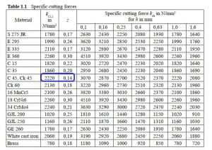
- Material to be processed: Steel C45
kc11 = 2220 N/mm2 |
; | z = 0.14 |
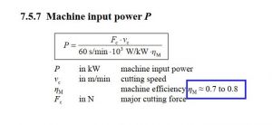
; | ηm = 0.7 |
Where: kc11: Unitary specific cutting force, z: material constant, ηm: machine efficiency
These values are obtained from the following sources[1]:
- Grinding process
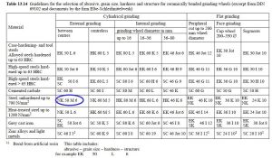
- Characteristics of the tool used
Cd = 11 USD |
; | Ded = 152.4 mm |
; | Did = 50 mm |
; | Lr = 25 mm |
; | Ded + Did
Dmr = ───────── = 101.2 mm
2
|
Where: Cd: Cost of an abrasive wheel, Ded: Abrasive wheel outside diameter, Did: Internal diameter of abrasive wheel (useful), Abrasive wheel thickness, Dmr: Median diameter of abrasive wheel. For these measurements, a commercial wheel was taken as a reference.
- Machining parameters
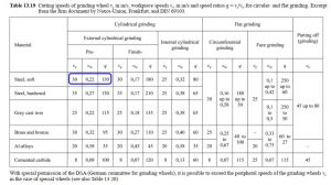
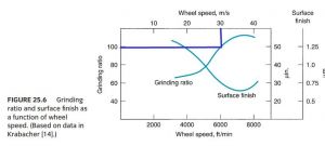
vr = 30 m/s |
; | vpr = 0.22 m/s |
; | q = vr / vpr = 136 |
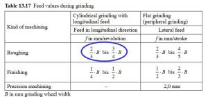
; | fr = 17.5 mm/rev |
; | dr = 0.01 mm |
     2 ⋅ vr
nr = ────── = 5662 rpm
       Dmr
|
; | 2 ⋅ vpr
npzr = ─────── = 133 rpm
Dmp
|
Where: vr: Abrasive wheel speed, vpr: Speed of the piece in grinding, q: velocity ratio; fr: Feed in grinding, dr: Depth of pass in grinding, nr: Rotational speed of abrasive wheel, npzr: Rotational speed of the piece in grinding
Sources[1]:
- Performance
       2 ⋅ (Lp + Lr)
t1pr = ───────────── = 6.4 s
         fr ⋅ npzr
|
; | Npr = prt / dr = 650 |
; | tppr = t1pr ⋅ Npr = 69 min |
; | Npsr = 1 week / tppr = 144 pieces/week |
Where: t1pr: Time of one pass in grinding, Npr: Number of passes in grinding, tppr: Time per piece in grinding, Npsr: Weekly production in grinding.
- Tooling cost
GR = 100 |
; | 2 2
Ded - Did Lr
Npd = GR ⋅ ─────────── ⋅ ── = 632 pieces/wheel
2 2 Lp
D1p - D2p
|
; | 1000
Cmpr = ──── ⋅ Cd = 17 USD
Npd
|
Where: GR: Grinding volume ratio, Npd: Quantity of pieces per abrasive wheel, Cmpr: Cost of abrasive wheels to make 1000 pieces
Sources[2]:
- Mechanical load
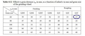
λke = 27 mm |
; | λke ___________________
hm = ─── ⋅ ╲╱dr ⋅ (1/Dmr + 1/Dmp) = 0.0041mm
q
|
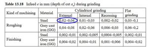
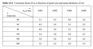
; | K = 3.43 |
z kc = (1mm/hm) ⋅ kc11 ⋅ K = 16500 N-mm2 |
; | b = 0.7 ⋅ Lr = 17.5 mm |
; | Ftr = b ⋅ hm ⋅ kc = 1174 N |
Where: λke: Effective grain distance, hm: Mean thickness of cut, K: Correction factor for grain size, kc: Specific cutting force, b: Effective grinding width, Ftr: Cutting force for grinding
Sources[1]:
               ___________________
    360°      ╱        dr
φ = ──── ⋅   ╱ ─────────────────── = 0.55°
      π    ╲╱  Dmr ⋅ (1 + Dmr/Dmp)
|
; | Dmr ⋅ π ⋅ φ
ze = ─────────── = 0.018
λke ⋅ 360°
|
; | Ftr ⋅ ze ⋅ vr
Potr = ───────────── = 1.217 hp
ηm
|
     Potr
Tr = ──── = 1.53 N-m
      nr
|
; | Ftr ⋅ Dmp
Ttr = ───────── = 18.5 N-m
2
|
; | Pottr = Ttr ⋅ npzr = 0.34 hp |
Where: φ: Angle of approach, ze: Number of cutting edges in contact, Potr: Absorbed power in grinding, Tr: Grinding torque, Ttr: Piece torque, Potr: Absorbed power in piece
- Turning process
- Characteristics of the tool used
Cc = 25 USD |
; | Naf = 10 |
; | vuc = 50 min |
Where: Cc Cost of a cutting tool, Naf: Number of sharps per tool, vuc: Lifespan of a sharp tool. For these data, a commercial cutting tool was taken as a reference.
- Machining parameters
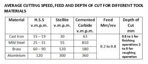
vt = 16 m/min |
; | ft = 0.5 mm/rev |
; | dt = 1 mm |
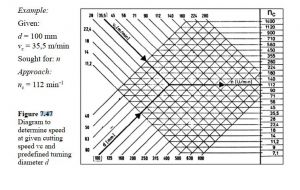
; | 2 ⋅ vt
nt = ────── = 134 rpm
D1p
|
Where: vt: Cutting speed in turning, ft: Feed in turning, dt: Depth of pass in turning, nt: Rotational speed in turning
Sources[3]:
- Performance
         Lp
t1pt = ─────── = 89 s
       ft ⋅ nt
|
; | Npt = prt / dt = 7 |
; | tppt = t1pt ⋅ Npt = 10 min |
; | Npst = 1 week / tppt = 1039 pieces/week |
Where: t1pt: Time of one pass in turning, Npt: Number of passes in turning, tppt: Time per piece in turning, Npst: Weekly production in turning.
- Tooling cost
       vuc
Npc = ──── ⋅ Naf = 51
      tppt
|
; | 1000
Cmpt = ──── ⋅ Cc = 485 USD
Npc
|
Where: Npc: Number of pieces per curring tool, Cmpt: Cost of tools to make 1000 pieces
- Mechanical load
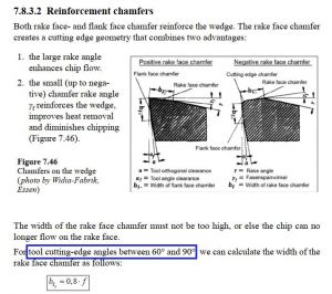
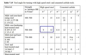
κ = 70° |
; | γ = 12° |
; | α = 8° |
; | h = ft ⋅ sin(κ) = 0.0748 mm |
; | Ac = dt ⋅ ft ⋅ rev = 0.5 mm2 |
; | γ - α
kγ = 1 - ───── = 0.999
100
|
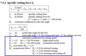
Kv = 1.15 |
; | Kst = 1 |
; | Kver = 1.3 |
; | z kc = (1mm / h) ⋅ kc11 ⋅ kγ ⋅ Kv ⋅ Kst ⋅ Kver = 4767 N/mm2 |
; | Ftt = Ac ⋅ kc = 2383 N |
nt2 = 140 rpm |
; | vt2 = nt2 ⋅ D1p = 33.4 m/min |
; | Ftt ⋅ vt2
Pott = ───────── = 2.54 hp
ηm
|
; | Pott
Tt = ──── = 129 N-m
nt2
|
Where: κ: cutting-edge angle, γ: Rake angle, α: Basic rake angle, h: Thickness of cut, Ac: Sectional area of chip, kγ: Rake coefficient, Kv: Speed coefficient, Kst: compression factor, Kver: wear factor, kc: Specific cutting force, Ftt: Cutting force, nt2: Standard speed, vt2: Real cutting speed, Pott: Input power in turning, Tt: Turning torque
Sources[1]:
Development and documentation - Technical solutions -- NVargas (talk) 01:59, 8 February 2023 (CET)
- AC motor for lathe: Preferred option , it can even be a three-phase motor.
- Cutting tool for lathe: Preferred option.
- Rotary stone with motor (cylindrical grinding): If you use it for roughing you will have a very low productivity, many passes are required to reduce the material.
- Bed and cross slide displacement with metal profiles (angle): Poor accuracy, for this equipment some precision is required, if you want a simple and accessible option, then a calibrated bar with bushings made of bronze works perfectly, I have done.
- After view some of the videos shown, the titled project “DIY lathe on metal made from scrap” is a very good reference:
- Simplicity, easily available materials and of course low cost.
- It is useful and doable for apprentices.
- In this case, the only thing I do not recommend is the used washing machine motors or the like.
- It would be very easy to add a tailstock to this project for the longer cylindrical pieces, such as tubes, bars, etc.
- Another recommendation is to use two good size bridge type pillow blocks for the 5" 4 jaw chuck.
- Regarding calculations and figures, I do not keep track of the different tests performed on these machines, so I recommend testing at all times.
- About the DIY chuck that is shown, it is very well developed in all its aspects, if it is considered that this person has a wide knowledge of what is related to turnery work, but it is not viable if you are not an expert in machining, it will be more easy and cheaper to buy this piece already manufactured.
- The DIY tailstok seems very feasible to manufacture this piece at home and with enough precision, using suitable and very common materials, such as: A good quality drill chuck, without the need to resort to sophisticated elements, such as those ER collars, Of course, it will also depend on the economic capacity of each person
Development and documentation - Technical solutions -- JMarques (talk) 02:30, 8 February 2023 (CET)
- A very important point in any grinding machine is the feed, the quality of the piece depends on this, the machine should have an automatic feed since:
- Very high can burn the piece
- Very low, can cause vibrations
- The feed must be thought at least counting on the use of square thread (Acme).
- Regarding the cutting medium, the grinding of cylindrical parts is generally applied for finishing processes, apart from conventional machining (with cutting tools), this to guarantee good production performance.
- This equipment is not recommended for a turnery due to the nature of its manufacture and the precision it could achieve, however it is feasible for small workshops related with:
- rubber rollers
- valve guides
- packaging machines
- injection systems
- kneading rollers
- among other similar
- Of the chucks shown, it is recommended to use the large one, to give it more capacity when processing long pieces, which is limited by the spindle hole, in any case.
- The chuck with four independent grinding wheels is preferred, although it requires more time to center, it has better grip
- Avoid misalignments and vibrations in the bench, through a robust construction and closed gaps
- For the centering of the free end, you can use a drill chuck on the tailstock or even make a steady rest with three screws.
- As an example of speeds in cylindrical grinding, to reduce 0.01mm in a piece, some typical speed values would be 40 rpm in the piece and 3600 rpm in the abrasive wheel.
Development and documentation - Technical solutions -- Xtech_2020 (talk) 05:15, 8 February 2023 (CET)
- According to some reviews done, the following factors must be taken into account in the design and construction of a cylindrical grinding machine:
- Abrasive motor requires high rotational speeds, in the order of 1:100 with respect to the piece, at least 3000 rpm;
- Abrasive motor requires high power, about 4 times the power of the main motor of the lathe.
- Due to the high speed of the abrasive, feed rate and depth of pass must be controlled so as not to exceed the power of the equipment, here are some experimental values of the forces that can be achieved for some grinding conditions.
- Use of angle grinder: Very low accuracy
- Use of linear bearings: High costs
- Purchased jaw chuck is my preferred option, a DIY chuck Self-centering requires CNC machining processes and a collet has limitations on diameter capacity
Development and documentation - Technical solutions -- Thehunter (talk) 07:01, 8 February 2023 (CET)
- An AC motor for the Lathe is preferred:
- Hand drill has a simpler design and speed can be adjusted, but presents problems with clamping and stability
- Cutting tools may not be the best option
- For lathe high forces are transmitted to the structure this point justifies the use of abrasives for cutting
- A Bench grinder is also preferable
- Simple design and offers high rotational speeds
- Bed and cross slide displacement with linear bearings may not withstand working forces
- A Purchased chuck is preferred
- The DIY chuck has no self-centering
- DIY tailstock manufactured is preferred
- With a manual, straight shank drill chuck
Notes
- Applied Machining Technology, Eighth Edition, Springer, 2008.
- Fundamentals of Modern Manufacturing: Materials, Processes, and Systems, Fourth Edition, JOHN WILEY & SONS, INC., 2010.
- CUTTING SPEED, FEED, DEPTH OF CUT, MACHINING TIME IN LATHE MACHINE Retrieved February 01, 2023.
- You can see a spreadsheet at this link

