CAD files
Definition
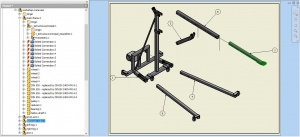
Once the Parts list has been approved by OHO, the developer proceeds to elaborate the CAD model package of the Project, this consists of developing the three-dimensional geometry of each part and defining the links between them to make up each assembly. This is done in the established CAD programs, among which are mentioned: Inventor, SolidWorks, Freecad, AutoCAD, and others
Guidelines
The CAD files must comply with the following guidelines
Structure
The package structure and file names must match the structure of the previously approved Parts list. The set of CAD files must be delivered in a zipped folder.
- The name of the compressed folder is defined, as in the Parts list, as follows:
- Organisation abbreviation, e.g. oseg for Open Source Ecology.
- Underscore separator '_'
- Project abbreviation, e.g. sp for Screw Press
- Underscore separator '_'
- Project name without spaces, example screw-press
- Complete example for the name: oseg_sp_screw-press.
- CAD files can be in the same root folder or organized according to their parts and assembly structure, containing the following hierarchy:
- A general assembly file [.iam]
- A general explosion or main subassembly separation file [.ipn]
- A sub-assembly1 (SE1) file [.iam]
- An SE1 explosion file [.ipn] (if applicable)
- A part1 file from SE1 [.ipt]
- A part2 file from SE1 [.ipt]
- ...
- A sub-assembly2 (SE2) file [.iam]
- An SE2 explosion file [.ipn] (if applicable)
- A part1 file of SE2 [.ipt]
- A part2 file of SE2 [.ipt]
- ...
Other aspects
- The extensions indicated are for Inventor, but the same hierarchy applies to other CAD systems.
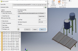
- In the case of Inventor, the Pack and Go tool can be used to generate the zipped folder with all its dependencies automatically.
- A zipped folder containing the CAD interchange files [.step/.stp] (one interchange file for each assembly or sub-assembly above [.iam]) must be generated.
- In case of changes in the structure or content of the files, OHO must be notified to update the Parts list and the CAD package by adding a two-level version suffix to the file name as in this example: oseg_sp_screw-press_1-01.
During the process of modeling parts and assemblies, the automation tools of the used programs should be used, as in the case of Inventor:
- Frame generator for metallic structures.
- Tube and Pipe for pipes.
- Bolt Join for bolted joints.
- Sheet metal for sheet metal parts.
- Among others, specific to the program and the version used.
This facilitates and optimizes subsequent processes such as structure analysis, pipe modifications, sheet thickness adjustments, among others.


